- Commercial Security Gates
 Cantilever Slide GatesSuper smooth operation. Browse our selection of cantilever slide gate designs.
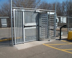
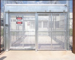
- Pedestrian PortalsProvide reliable entry and exit control to all types of secure and restricted areas.
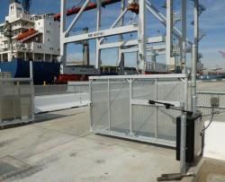
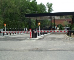
- Automated Security Gate SystemsSecurity gates with integrated operators.
- Heavy Duty Swing Gate*Closes single clear openings up to 35 feet wide.
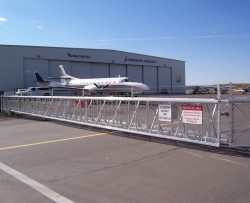
- Huge GatesFor very large clear openings that require a high level of security.
- Vertical Lift Gate*Standard design closes single clear openings up to 60 feet wide.
- Overhead GatesRugged, reliable, low maintenance protection for high cycle applications in extreme climates or limited space.
- Custom Gate DesignsWork directly with our design, specification, and engineering teams to design your own custom solution.
- Pedestrian Swing GatesSafeguard points of pedestrian ingress and egress.
- SecurFold Bi-Folding Speed GateIndependently tested and certified to 200,000 cycles.
- Crash Barriers
- Correctional Systems
- Markets
- Specifications & Drawings
- Fabrication Solutions
- About
- Contact TYMETAL


Downloads Page for TYM VS2-1B Box Frame Gate System
Gate Brochure
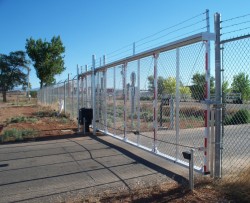
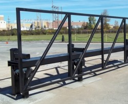
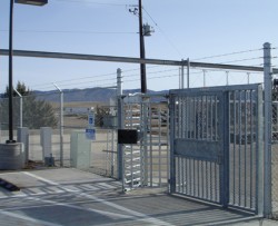
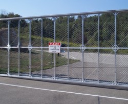
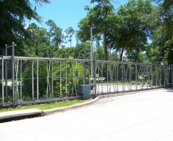
The Fortress Box Frame Slide Gate, manufactured by TYMETAL, is a cantilever system designed to handle the forces of gravity and wind, using box frame construction and stainless steel cable. Diagonal cross members eliminate lateral sway while numerous design features are necessary for single gates with widths up to 60 feet, 120 feet for doubles, addressing potential stresses on the gate.
Box Frame Gates are fabricated from 6063-T6 aluminum alloy extrusions with primary members (top and bottom) “P” shaped in the cross-section. The vertical members alternate between 2”x 2” and 1”x 2” in cross section and are spaced at a distance not to exceed the overall height of the box frame. Constructed in “box” form, the width between the frames measures 24” from outside to outside.
Each frame has a track of extruded aluminum alloy welded to the primary member allowing the gate to operate smoothly. The gate frame is supported from the two tracks by fourself-aligning, 4-wheeled, sealed lubricant ball-bearing truck assemblies. The gate includes cross bracing of 3/16” minimum diameter stainless steel cable to provide for vertical adjustment.
For special applications with limited backspace or larger openings, telescoping or roller box frame gates are also available.
Operator Brochure
APeX Controller
• UL325/UL991 compliant 24VDC control module
• Full featured for access control, security, and entrapment protection
• Integral MegaCode receiver
• On-board 3-button station
Heavy Duty Braking
• Double c-face, dual disk electromagnetic brake
Heavy Duty Components
• Adjustable torque-limiter and heavy-duty pillow block bearings for smooth, reliable, quiet power transmission
• All models are rated for continuous duty
Variable Drive Speed
• Programmable variable speed controller for smooth gate operation and high gate speed.
• Soft start. stop programmable
Manual Hand Crank
• Crank handle can be folded out and used for emergency manual operation to crank the gate open and closed
Weather Resistant Cabinet
• Galvanized steel cabinet with powder-coated finish. The removable front cover is hinged, gasketed, and lockable Standard Convenience Features
• Power on/off button
• Exterior stop/reset button
Direct C-Face Motor-Brake-Gear Box Drive
• Designed for smooth and dependable power transmission
ELECTRICAL
• Diagnostic LED display for ease of setup and troubleshooting
• 1 HP industrial, continuous duty, 1& 3 phase 56 frame motors
• Integral entrapment sensing system with digital set point for accurate adjustment and enhanced safety
• Built-in dual gate capability using
3-wire shielded cable
• 24V DC power available for access control accessories
• Continuous-tone entrapment alarm with reset button
• Integrated warning beeper during gate movement
MECHANICAL
• Heavy duty 15:1 right angle C-face gear reducer
• #50 roller chain and sprockets
• Heavy-duty steel chassis
• Heavy-duty pillow-block bearings
• Adjustable torque limiter
CAUTIONS
• Automatic gates not for pedestrians
• Automatic gate operators designed for vehicular traf?c only; operators are powerful and can cause serious injury or death; DIRECT ALL PEDESTRIAN TRAFFIC TO SEPARATE PEDESTRIAN GATE
• UL 325 requires the use of contact or non-contact anti-entrapment devices
• ASTM F2200 requires that all exposed rollers are covered
Specification Section 32 31 00
BOX FRAME CANTILEVER SLIDE GATE SYSTEM WITH
TYM-VS2-1 VARIABLE SPEED OPERATOR
(CHAIN LINK)
PART 1 – GENERAL:
1.01 SECTION INCLUDES:
A. The work in this section shall include furnishing all labor, materials, equipment and appliances necessary to complete all Fortress TYM-VS2-1 Box Frame Gate System(s) required for this project in strict accordance with this specification section and drawings. The gate and operator shall be specifically designed to complement each other as a system and be provided by a single manufacturer. Components (operator from one source and gate panel from another) assembled at the job site to form a system will not be approved.
1.02 REFERENCES:
A. UL 325 Gate Operator Requirements. See 2.01 C.
1. Automated / operated vehicular gates are not to be used for pedestrian traffic. Separate pedestrian gates must always be provided if pedestrian traffic is expected.
B. ASTM F 2200 Standard Specification for Automated Vehicular Gate Construction. See 2.01 C.
C. ASTM F 1184 Standard Specification for Industrial and Commercial Horizontal Slide Gates, Type II, Class 2. See 3.02 B.
D. American Welding Society AWS D1.2 Structural Welding Code. See 2.01 B.
1.03 SUBMITTAL:
A. Product Data:
1. Provide manufacturer’s catalog cuts with printed specifications and installation instructions.
2. Deliver two copies of operation and maintenance data covering the installed products. Manual to include parts list showing manufacturer’s names and part numbers for the gate operator.
B. Shop Drawings:
1. Supply shop drawings showing the relationship of operating systems with gate components, including details of all major components.
2. Include complete details of gate construction, gate height and post spacing dimensions.
C. Certification of Performance Criteria:
1. Manufacturer of gate system shall provide certification stating the gate system includes the following material components that provide superior performance and longevity. Alternate designs built to minimum standards that do not include these additional structural features shall not be accepted.
a. Gate track system shall be keyed to interlock into gate frame member (providing 200% additional strength when compared to weld-only keyless systems). When interlocked with and welded to the “keyed” frame top member, gate track forms a composite structure.
b. Gate shall have a minimum counterbalance length of 50% opening width which provides a 36% increase in lateral resistance (when compared to ASTM minimum of 40% counterbalance). If the gate is ever to be automated, the counterbalance section shall be filled with fabric or other specified material.
c. To provide superior structural integrity, intermediate vertical members shall be used – with spacing between verticals to be less than 50% of the gate frame height.
d. Entire gate frame (including counterbalance section) shall include 2 adjustable stainless steel cables (minimum 3/16”) per bay to allow complete gate frame adjustment (maintaining strongest structural square and level orientation).
e. Gate truck assemblies shall be tested for continuous duty and shall have precision ground and hardened components. Bearings shall be pre-lubricated and contain shock resistant outer races and captured seals.
f. Gate truck assemblies shall be supported by a minimum 5/8” plated steel bolt with self-aligning capability, rated to support a 2,000 # reaction load.
g. Hanger brackets shall be hot-dipped galvanized steel with a minimum 3/8” thickness that is also gusseted for additional strength.
h. Gate top track and supporting hangar bracket assemblies shall be certified by a licensed professional engineer to withstand a 2,000 lb. vertical reaction load without exceeding allowable stresses.
D. Certifications:
1. Gate in compliance with ASTM F 2200, Standard Specification for Automated Vehicular Gate Construction per section 2.01 C.
2. If operated gate system, gate operator shall be in compliance with UL 325 as evidenced by UL listing label attached to gate operator.
3. The aluminum welders and welding process must be certified per section 2.01 B.
4. Manufacturer shall supply gate design performance certification as per section 1.03 C.
PART 2 – PRODUCTS:
2.01 CANTILEVER SLIDE GATE SYSTEM MANUFACTURERS:
A. The cantilever sliding gate system shall be manufactured by TYMETAL, 2549 State Route 40, Greenwich, NY 12834 (800) 328 4283.
B. Gate manufacturer shall provide independent certification as to the use of a documented Welding Procedure Specification and Procedure Qualification Record to insure conformance to the AWS D1.2 welding code. Upon request, Individual Certificates of Welder Qualification documenting the successful completion of the requirements of the AWS D1.2 code shall also be provided. See 1.02 D.
C. Gate manufacturer shall certify gate is manufactured in compliance with ASTM F 2200, Standard Specification for Automated Vehicular Gate Construction and the operators are UL 325 compliant. See 1.03 D.1 and 103.D.2.
2.02 VEHICULAR SLIDE GATE OPERATOR TYM-VS2-1:
A. The slide gate operator as provided by TYMETAL shall open and close cantilever, overhead, or track gates, to provide convenience and security. This model is adapted to function with most accessories including radio controls, electro-mechanical locks, single and three button control stations, digital keypads, coded cards, sensing loops, telephone entry systems, and revenue control equipment. The operator utilizes 208/230 Volt AC single phase or 208/230/460 Volt AC three phase power. The control voltage in each case is 24 Volt DC.
B. The gate operator includes an APeX Controller with an integrated radio receiver, plug-in loop detector capability, surge protection, and easy-to-read labeling standard.
C. Capacity:
1. The gate operator shall be rated to operate a gate weighing up to 2500 lbs.
D. The gate operator shall be UL 325 compliant for Class III and IV.
E. Design Criteria:
1. Operation shall be by means of a 1HP pulse width modulated variable frequency instant reversing motor, transferring power to a heavy-duty right angle oil bath gear reducer. Power is transferred from the gear reducer to a heavy-duty torque limiter and a #40 plate sprocket. The torque limiter transfers power to the output shaft equipped with a #50 drive sprocket and roller chain which attaches to the gate with heavy-duty gate attachment brackets. The intermediate chain supports with an anti-catch design shall also be supplied. Manual operation shall be by means of an integral foldout hand crank.
2. The operator shall include a soft start, soft stop and adjustable speed feature. The operator shall open and close the gate at a speed up to 24 inches per second.
3. The #50 chain shall be coated with “Armor Coat” corrosive resistant chain coating. Corrosive resistance exceeds nickel plating.
F. Components:
1. Standard mechanical components shall include as a minimum.
a. 14 gauge, weather-resistant galvanized and powder-coated steel cabinet with a gasketed cover which is fully removable and lockable.
b. Post mounting standard.
c. Heavy duty right angle oil bath C-face gear reducer.
d. One inch solid steel output drive shaft.
e. Heavy duty pillow block bearings with grease fittings.
f. Heavy duty 5 inch diameter torque limiter.
g. Dual C-face foot pound brake.
h. Integral foldout hand crank for emergency manual operation.
i. All welded interior steel framework.
2. Standard electrical components shall include as a minimum:
a. 1 HP motor with thermal overload protection.
b. Solid state logic controls featuring 15 diagnostic L.E.D. indicators and auto-close timer (1second to 9 minutes).
c. Inherent, fully adjustable motor over-current sensing to detect obstructions via precision 24 turn potentiometer, with separate adjustments for opening and closing directions.
d. Controller housed in zinc plated control box with separate box provided for connection of field power.
e. Power On/Off switch.
f. Contacts for opening, closing and reversing accessories, as well as contact and non-contact obstruction sensing devices. 24 VAC and 24 VDC available on terminal strip to power accessory devices, provided by non-circuit board mounted transformer with minimum 75VA rating.
g. Adjustable limits with precision snap-action type limit switches to control gate position and variable speed control.
h. Master/slave or stand-alone capable with dip switch selection. Three wire twisted pair shielded cable required.
3. Optional components:
a. Arctic Package – includes thermostatically controlled heater and artic gearbox oil.
4. Optional accessories, contact, non-contact, and control devices:
a. Control devices include pushbuttons, radio controls, keypads, card readers, key switches, telephone entry systems, and revenue control equipment.
b. Contact and non-contact devices include photoelectric sensors, vehicle detectors, proximity sensors, and contact edges.
c. Accessories include flashing strobe lights, cycle counters, and intercom systems.
G. Factory Inspection and Testing
1. Manufacturer shall test each operator at the factory to assure smooth, quiet operation.
2. Manufacturer shall test all control inputs to ensure proper function.
2.03 GATE CONSTRUCTION DETAILS:
A. The gate frames shall be fabricated from 6063-T6 aluminum alloy extrusions. If fabricated as a single horizontal piece, no splices will be required. When the gate frame is manufactured in two horizontal pieces or sections, they shall be spliced in the field (the gate frame shall be fabricated in one or multiple sections depending on size requirements or project constraints).
1. The primary members (top and bottom) shall be “P” shaped in cross-section with no less than 2″ on a side and weighing not less than 1.6 lb/lf. To maintain structural integrity this top member shall be “keyed” to interlock with a “keyed” track member.
B. Vertical Members:
1. End vertical members of the gate frame are 2”x2”, weighing not less than 1.1 lb/lf. Interior vertical members shall alternate between 1″x1″ and 1″x2″ in cross-section, weighing not less than .52 lb/lf and .82 lb/lf respectively. The 1”x2” and 1”x1” intermediate vertical members shall be spaced at a distance not to exceed the overall height of the box frame. The gate shall be constructed in “box” form with the width between the frames measuring 24″ from outside to outside. Between these frames there shall be a continuous series of 1″x1″ diagonal and horizontal bracing with the diagonals welded at approximately 45 degrees to the frames.
C. Gate Track:
1. The gate shall have a separate semi-enclosed “keyed” track, extruded from 6005A-T61 or 6105 T5 aluminum alloy, weighing not less than 2.9 lb/lf. Track members are to be located on each side of the top member. When interlocked and welded to the “keyed” top member, it forms a composite structure with the top of the gate frame. Welds are to be placed alternately along the top and side of the track at 9″ centers with welds being a minimum of 2″ long.
D. All welds on the gate frame shall conform to Welding Procedure Specification and Procedure Qualification Record to insure conformance to the AWS D1.2 Structural Welding Code. All individual welders shall be certified to AWS D1.2 welding code. See 1.02 D.
E. Gate Mounting:
1. The gate frame is to be supported from the track by four (4) swivel type, self-aligning, 4 wheeled, sealed lubricant, ball-bearing truck assemblies.
2. The bottom of each support post shall have a bracket equipped with a pair of 3” (76mm) UHMW guide wheels Wheel cover protectors shall be included with bottom guides to comply with UL325.
3. Gap protectors shall be provided and installed, compliant with ASTM F 2200.
F. Diagonal Bracing:
1. Diagonal “X” bracing of 3/16″ (5mm) minimum diameter stainless steel aircraft cable shall be installed throughout the entire gate frame.
G. The gate shall be completed by installation of approved filler as specified.
1. Chain Link: 2” x 2” x 9 gauge aluminized steel chain link fabric shall extend the entire length of the gate (if operated gate, counterbalance must also have fabric to prevent reach through and comply with ASTM F2200, see 1.03 C.1) Fabric shall be attached at each end of the gate frame by standard fence industry tension bars and tied at each 2” x 2” (51mm x 51mm) vertical member with standard fence industry ties. ASTM F2200 requires attachment method that leaves no leading or bottom edge protrusions (cannot exceed 0.5 inch).
H. Posts (by others):
1. Double sets of support posts shall be a minimum of 4″ O.D. (102mm) round Schedule 40 or 4” x 4” x 3/16” wall square steel tubing, grade 500. Gate posts shall be galvanized or coated and supported in concrete footings as specified by the design team.
I. Finish:
1. Gate to be mill finish aluminum or color coated with polyester powder as specified. If powder coated, the gate (including track member) and all accessories shall be pretreated chemically by sand blasting or other acceptable method to ensure proper coating adherence. Gate posts (to be supplied by others) shall be galvanized or coated as specified by the design team .
J. Gate Lock (Optional):
1. Gate system shall be furnished with an electro-mechanical lock. The lock shall be supplied with status indication and with a six-tumbler mechanical lock. All gates shall be keyed alike. Lock requires additional 115V power supplied by others.
2.04 WARRANTY:
A. The cantilever slide gate and operator system shall be warranted by the manufacturer against manufacturing defects for a period of (3) three years from date of sale. The truck assembly shall be warranted against manufacturing defects by the manufacturer for a period of (5) five years from date of sale.
PART 3 – EXECUTION:
3.01 SITE INSPECTION:
A. Examine final grades and installation conditions.
B. Do not begin work until all unsatisfactory conditions are corrected.
3.02 INSTALLATION:
A. Install equipment of this section in strict accordance with the company’s printed instructions unless otherwise shown on the contract drawings.
B. The gate and installation shall conform to ASTM F 1184 standards for aluminum cantilever slide gates, Type II, Class 2. See 1.02 C.
C. The gate system is to comply with ASTM F 2200 and UL 325. See 1.02 B and 1.02 A respectively.
D. Obstruction Sensing Systems:
1. The inherent motor current sensors are part of the gate operator system and may not be removed or bypassed.
2. The installing contractor shall be responsible to ensure that appropriate external secondary entrapment protection devices be installed for the specific site conditions to protect against all potential entrapment zones. Proper operation of these safety devices shall be verified and training as to the operation and maintenance of these devices for the users and owners shall be documented.
3.03 SYSTEM ACCEPTANCE & VALIDATION:
A. Acceptance Test:
1. Test each system function.
2. Supply all equipment necessary for system adjustment and testing.
B. Test and Explain Safety Features:
1. Each system feature and device is a separate component of the gate system.
2. Read and follow all instructions for each component.
3. Ensure that all instructions for mechanical components, safety devices and the gate operator are available for everyone who will be using the gate system.
4. The warning signs shipped with the gate operator must be installed in prominent position on both sides of the gate.
C. System Validation:
1. The complete system shall be adjusted to assure it is performing properly.
2. The system shall be operated for a sufficient period of time to determine that the system is in proper working order.
3. Ensure the owner is clear with regard to the safety points concerning the basic operational guidelines of the safety features of the gate operator system. These safety points are listed in the operator manual and must be read prior to system use.
4. Installer and customer shall complete Operated Gate System Installation Checklist (see operator manual).
Note: TYMETAL reserves the right to modify and/or make changes as deemed necessary without previous notice.
Specification Section 32 31 00
BOX FRAME CANTILEVER SLIDE GATE SYSTEM WITH
TYM-VS2-1 VARIABLE SPEED OPERATOR
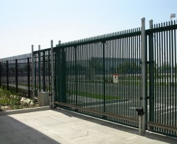
(ORNAMENTAL)
PART 1 – GENERAL:
1.01 SECTION INCLUDES:
A. The work in this section shall include furnishing all labor, materials, equipment and appliances necessary to complete all Fortress TYM-VS2-1 Box Frame Gate System(s) required for this project in strict accordance with this specification section and drawings. The gate and operator shall be specifically designed to complement each other as a system and be provided by a single manufacturer. Components (operator from one source and gate panel from another) assembled at the job site to form a system will not be approved.
1.02 REFERENCES:
A. UL 325 Gate Operator Requirements. See 2.01 C.
1. Automated / operated vehicular gates are not to be used for pedestrian traffic. Separate pedestrian gates must always be provided if pedestrian traffic is expected.
B. ASTM F 2200 Standard Specification for Automated Vehicular Gate Construction. See 2.01 C.
C. ASTM F 1184 Standard Specification for Industrial and Commercial Horizontal Slide Gates, Type II, Class 2. See 3.02 B.
D. American Welding Society AWS D1.2 Structural Welding Code. See 2.01 B.
1.03 SUBMITTAL:
A. Product Data:
1. Provide manufacturer’s catalog cuts with printed specifications and installation instructions.
2. Deliver two copies of operation and maintenance data covering the installed products. Manual to include parts list showing manufacturer’s names and part numbers for the gate operator.
B. Shop Drawings:
1. Supply shop drawings showing the relationship of operating systems with gate components, including details of all major components.
2. Include complete details of gate construction, gate height and post spacing dimensions.
C. Certification of Performance Criteria:
1. Manufacturer of gate system shall provide certification stating the gate system includes the following material components that provide superior performance and longevity. Alternate designs built to minimum standards that do not include these additional structural features shall not be accepted.
a. Gate track system shall be keyed to interlock into gate frame member (providing 200% additional strength when compared to weld-only keyless systems). When interlocked with and welded to the “keyed” frame top member, gate track forms a composite structure.
b. Gate shall have a minimum counterbalance length of 50% opening width which provides a 36% increase in lateral resistance (when compared to ASTM minimum of 40% counterbalance). If gate is ever to be automated, the counterbalance section shall be filled with fabric or other specified material.
c. To provide superior structural integrity, intermediate vertical members shall be used – with spacing between verticals to be less than 50% of the gate frame height.
d. Entire gate frame (including counterbalance section) shall include 2 adjustable stainless steel cables (minimum 3/16”) per bay to allow complete gate frame adjustment (maintaining strongest structural square and level orientation).
e. Gate truck assemblies shall be tested for continuous duty and shall have precision ground and hardened components. Bearings shall be pre-lubricated and contain shock-resistant outer races and captured seals.
f. Gate truck assemblies shall be supported by a minimum 5/8” plated steel bolt with self-aligning capability, rated to support a 2,000 # reaction load.
g. Hanger brackets shall be hot-dipped galvanized steel with a minimum 3/8” thickness that is also gusseted for additional strength.
h. Gate top track and supporting hangar bracket assemblies shall be certified by a licensed professional engineer to withstand a 2,000 lb. vertical reaction load without exceeding allowable stresses.
D. Certifications:
1. Gate in compliance with ASTM F 2200, Standard Specification for Automated Vehicular Gate Construction per section 2.01 C.
2. If operated gate system, gate operator shall be in compliance with UL 325 as evidenced by UL listing label attached to gate operator.
3. The aluminum welders and welding process must be certified per section 2.01 B.
4. Manufacturer shall supply gate design performance certification as per section 1.03 C.
PART 2 – PRODUCTS:
2.01 CANTILEVER SLIDE GATE SYSTEM MANUFACTURERS:
A. The cantilever sliding gate system shall be manufactured by TYMETAL, 2549 State Route 40, Greenwich, NY 12834 (800) 328 4283.
B. Gate manufacturer shall provide independent certification as to the use of a documented Welding Procedure Specification and Procedure Qualification Record to insure conformance to the AWS D1.2 welding code. Upon request, Individual Certificates of Welder Qualification documenting the successful completion of the requirements of the AWS D1.2 code shall also be provided. See 1.02 D.
C. Gate manufacturer shall certify gate is manufactured in compliance with ASTM F 2200, Standard Specification for Automated Vehicular Gate Construction and the operators are UL 325 compliant. See 1.03 D.1 and 103.D.2.
2.02 VEHICULAR SLIDE GATE OPERATOR TYM-VS2-1:
A. The slide gate operator as provided by TYMETAL shall open and close cantilever, overhead, or track gates, to provide convenience and security. This model is adapted to function with most accessories including: radio controls, electro-mechanical locks, single and three button control stations, digital keypads, coded cards, sensing loops, telephone entry systems, and revenue control equipment. The operator utilizes 208/230 Volt AC single phase or 208/230/460 Volt AC three phase power. Control voltage in each case is 24 Volt DC.
B. The gate operator includes an APeX Controller with integrated radio receiver, plug-in loop detector capability, surge protection, and easy to read labeling standard.
C. Capacity:
1. The gate operator shall be rated to operate a gate weighing up to 2500 lbs.
D. The gate operator shall be UL 325 compliant for Class III and IV.
E. Design Criteria:
1. Operation shall be by means of a 1HP pulse width modulated variable frequency instant reversing motor, transferring power to a heavy duty right angle oil bath gear reducer. Power is transferred from the gear reducer to a heavy duty torque limiter and a #40 plate sprocket. The torque limiter transfers power to the output shaft equipped with a #50 drive sprocket and roller chain which attaches to the gate with heavy-duty gate attachment brackets. Intermediate chain supports with anti-catch design shall also be supplied. Manual operation shall be by means of an integral foldout hand crank.
2. The operator shall include a soft start, soft stop and adjustable speed feature. The operator shall open and close the gate at a speed up to 24 inches per second.
3. The #50 chain shall be coated with “Armor Coat” corrosive resistant chain coating. Corrosive resistance exceeds nickel plating.
F. Components:
1. Standard mechanical components shall include as a minimum.
a. 14 gauge, weather resistant galvannealed and powder coated steel cabinet with a gasketed cover which is fully removable and lockable.
b. Post mounting standard.
c. Heavy duty right angle oil bath C-face gear reducer.
d. One inch solid steel output drive shaft.
e. Heavy duty pillow block bearings with grease fittings.
f. Heavy duty 5 inch diameter torque limiter.
g. Dual C-face foot pound brake.
h. Integral foldout hand crank for emergency manual operation.
i. All welded interior steel framework.
2. Standard electrical components shall include as a minimum:
a. 1 HP motor with thermal overload protection.
b. Solid state logic controls featuring 15 diagnostic L.E.D. indicators and auto-close timer (1second to 9 minutes).
c. Inherent, fully adjustable motor over-current sensing to detect obstructions via precision 24 turn potentiometer, with separate adjustments for opening and closing directions.
d. Controller housed in zinc plated control box with separate box provided for connection of field power.
e. Power On/Off switch.
f. Contacts for opening, closing and reversing accessories, as well as contact and non-contact obstruction sensing devices. 24 VAC and 24 VDC available on terminal strip to power accessory devices, provided by non-circuit board mounted transformer with minimum 75VA rating.
g. Adjustable limits with precision snap-action type limit switches to control gate position and variable speed control.
h. Master/slave or stand alone capable with dip switch selection. Three wire twisted pair shielded cable required.
3. Optional components:
a. Arctic Package – includes thermostatically controlled heater and artic gearbox oil.
4. Optional accessories, contact, non-contact, and control devices:
a. Control devices include pushbuttons, radio controls, keypads, card readers, key switches, telephone entry systems, and revenue control equipment.
b. Contact and non-contact devices include photoelectric sensors, vehicle detectors, proximity sensors, and contact edges.
c. Accessories include flashing strobe lights, cycle counters, and intercom systems.
G. Factory Inspection and Testing
1. Manufacturer shall test each operator at factory to assure smooth, quiet operation.
2. Manufacturer shall test all control inputs to ensure proper function.
2.03 GATE CONSTRUCTION DETAILS:
A. The gate frames shall be fabricated from 6063-T6 aluminum alloy extrusions. If fabricated as a single horizontal piece, no splices will be required. When the gate frame is manufactured in two horizontal pieces or sections, they shall be spliced in the field (the gate frame shall be fabricated in one or multiple sections depending on size requirements or project constraints).
1. The primary members (top and bottom) shall be “P” shaped in cross section with no less than 2″ on a side and weighing not less than 1.6 lb/lf. To maintain structural integrity this top member shall be “keyed” to interlock with a “keyed” track member.
B. Vertical Members:
1. End vertical members of the gate frame are 2”x2”, weighing not less than 1.1 lb/lf. Interior vertical members shall alternate between 1″x1″ and 1″x2″ in cross section, weighing not less than .52 lb/lf and .82 lb/lf respectively. The 1”x2” and 1”x1” intermediate vertical members shall be spaced at a distance not to exceed the overall height of the box frame. The gate shall be constructed in “box” form with the width between the frames measuring 24″ from outside to outside. Between these frames there shall be a continuous series of 1″x1″ diagonal and horizontal bracing with the diagonals welded at approximately 45 degrees to the frames.
C. Gate Track:
1. The gate shall have a separate semi-enclosed “keyed” track, extruded from 6005A-T61 or 6105 T5 aluminum alloy, weighing not less than 2.9 lb/lf. Track members are to be located on each side of the top member. When interlocked and welded to the “keyed” top member, it forms a composite structure with the top of the gate frame. Welds are to be placed alternately along the top and side of the track at 9″ centers with welds being a minimum of 2″ long.
D. All welds on the gate frame shall conform to Welding Procedure Specification and Procedure Qualification Record to insure conformance to the AWS D1.2 Structural Welding Code. All individual welders shall be certified to AWS D1.2 welding code. See 1.02 D.
E. Gate Mounting:
1. The gate frame is to be supported from the track by four (4) swivel type, self-aligning, 4 wheeled, sealed lubricant, ball-bearing truck assemblies.
2. The bottom of each support post shall have a bracket equipped with a pair of 3” (76mm) UHMW guide wheels Wheel cover protectors shall be included with bottom guides to comply with UL325.
3. Gap protectors shall be provided and installed, compliant with ASTM F 2200.
F. Diagonal Bracing:
1. Diagonal “X” bracing of 3/16″ (5mm) minimum diameter stainless steel aircraft cable shall be installed throughout the entire gate frame.
G. The gate shall be completed by installation of approved filler as specified.
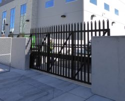
1. Ornamental Picket: Picket sizes shall be 1” (25mm) square. Pickets may extend through only the clear opening portion or through the entire length of the gate as required. If a motorized gate operator is to be applied to the gate and the specified picket spacing allows for openings in the gate frame that exceed 2¼” (57mm), a secondary gate filler shall be secured at each end of the gate frame and tied at each 1” x 2” (25mm x 51mm) or 2” x 2” (51mm x 51mm) vertical member. The secondary gate filler shall extend to a minimum height of 72” (1.2m) above grade and shall be sized to prevent a 2¼” (57mm) diameter sphere from passing through openings anywhere along the length of the gate frame and in that portion of the adjacent fence that the gate covers in the open position.
H. Posts (by others):
1. Double sets of support posts shall be a minimum 4″ O.D. (102mm) round Schedule 40 or 4” x 4” x 3/16” wall square steel tubing, grade 500. Gate posts shall be galvanized or coated and supported in concrete footings as specified by the design team.
I. Finish:
1. Gate to be mill-finished aluminum or color coated with polyester powder as specified. If powder coated, the gate (including track member) and all accessories shall be pretreated chemically by sand blasting or other acceptable method to ensure proper coating adherence. Gate posts (to be supplied by others) shall be galvanized or coated as specified by the design team.
J. Gate Lock (Optional):
1. Gate system shall be furnished with an electro-mechanical lock. The lock shall be supplied with status indication and with a six-tumbler mechanical lock. All gates shall be keyed alike. Lock requires additional 115V power supplied by others.
2.04 WARRANTY:
A. The cantilever slide gate and operator system shall be warranted by the manufacturer against manufacturing defects for a period of (3) three years from the date of sale. The truck assembly shall be warranted against manufacturing defects by the manufacturer for a period of (5) five years from the date of sale.
PART 3 – EXECUTION:
3.01 SITE INSPECTION:
A. Examine final grades and installation conditions.
B. Do not begin work until all unsatisfactory conditions are corrected.
3.02 INSTALLATION:
A. Install equipment of this section in strict accordance with the company’s printed instructions unless otherwise shown on the contract drawings.
B. The gate and installation shall conform to ASTM F 1184 standards for aluminum cantilever slide gates, Type II, Class 2. See 1.02 C.
C. The gate system is to comply with ASTM F 2200 and UL 325. See 1.02 B and 1.02 A respectively.
D. Obstruction Sensing Systems:
1. The inherent motor current sensors are part of the gate operator system and may not be removed or bypassed.
2. The installing contractor shall be responsible to ensure that appropriate external secondary entrapment protection devices be installed for the specific site conditions to protect against all potential entrapment zones. Proper operation of these safety devices shall be verified and training as to the operation and maintenance of these devices for the users and owners shall be documented.
3.03 SYSTEM ACCEPTANCE & VALIDATION:
A. Acceptance Test:
1. Test each system function.
2. Supply all equipment necessary for system adjustment and testing.
B. Test and Explain Safety Features:
1. Each system feature and device is a separate component of the gate system.
2. Read and follow all instructions for each component.
3. Ensure that all instructions for mechanical components, safety devices and the gate operator are available for everyone who will be using the gate system.
4. The warning signs shipped with the gate operator must be installed in a prominent position on both sides of the gate.
C. System Validation:
1. The complete system shall be adjusted to assure it is performing properly.
2. The system shall be operated for a sufficient period of time to determine that the system is in proper working order.
3. Ensure the owner is clear with regard to the safety points concerning the basic operational guidelines of the safety features of the gate operator system. These safety points are listed in the operator manual and must be read prior to system use.
4. Installer and customer shall complete Operated Gate System Installation Checklist (see operator manual).
Note: TYMETAL reserves the right to modify and/or make changes as deemed necessary without previous notice.